|
|
| If you have already studied our tutorial concerning the assembly and animation of a little robot model then you actually know everything regarding Forward Kinematics - a hierarchy of objects with their object-axes serving as joints and points of rotation. Then, rotating an object about its object-axes will cause all hierarchical subordinated objects to follow the rotation. This is called Forward Kinematics. Inverse Kinematics can simplify the positioning of several joints simultaneously even more. You need only to pull on a finger, for example, to stretch the complete arm of a 3D-model - similar to a real jointed puppet.
|
| Furthermore you can restrict the rotation angles for each joint by setting limits for each individual rotation axes (Degrees of Freedom), thus preventing the model from unnatural twisted movements.
|
|
|
| Forward Kinematics (FK) or Inverse Kinematics (IK) is applied only in "Move Object" work mode.
|
|
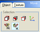
| In the tool window, beneath the 3 selection buttons for selecting objects, facets or individual points there are 2 additional buttons for the |
|
|
| In practice: (You can find corresponding sample files to all examples in the folder "\projects\ik\".)
|
|
|
|
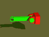
| First we load a simple hinge object "root" with a lever object "arm_1" attached to it (project file "ik_1_joint.cmo"). The hinge serves as root object for the hierarchy and is not movable itself. To prevent the hinge from taking part in the rotation movements of its subordinated joints we mark the hinge object and then, clicking with the right mouse button into a viewport window, call up the popup selection and select the "properties" entry.
|
|
|
|
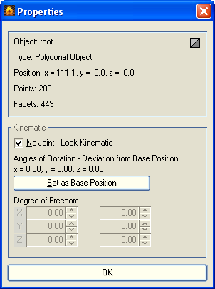
| In the upper part of the "Properties" window some basic information about the selected object is provided, while in the lower part all settings for Kinematics can be arranged. Switch on now the <No Joint - Lock Kinematic> function for our hinge object "root". This results in a fixed hinge that will not rotate, when pulling at subordinated objects belonging to it.
|
|
|
|
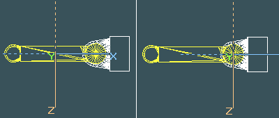
| Next we select object "arm1". The rotations of the objects are always executed about a defined pivot point, which is identical to the focus of the object-axes. So first we have to move the object-axes of the "arm1" object to the joint position, about which the individual rotations are later executed (shown in the right illustration above). Select therefore in "Move Object" work mode the object axes selection.
|
| Now you can easily move the axes system with the mouse to the desired joint position.
|
|
|
| Click with the left mouse button on "arm1" . While holding down the button a box containing the name of the object appears. Drag the box over the "root" object until a tool-tip indicating "Link" appears. Release the button and "arm1" is now displayed to the right side of the "root" in the window and is subordinate to that object.
|
| Now we can return to "Move Object" work mode for our first test on Kinematics. Activate the Inverse Kinematics work mode by selecting the |
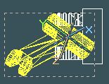 (Top view) (Top view)
|
| If you select now "arm1" and pull at the object, it really tries to follow the mouse movement by rotating about its object-axes. However, it rotates about all 3 object-axes and therefore it breaks out off the hinge. Consequently we have to restrict the possible rotations to that axis, that goes straight through the openings of the hinge object, in our example this is the y-axis of the "arm1" object.
|

|
| Use the <Undo> function to return to the initial position of "arm1". Then call up again the "Properties" dialog.
|
|
|
|
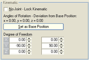
| Use the "Degree of Freedom" (DOF) parameters to adjust for each rotation axis a lower and an upper limit within that the object can be rotated. These limiting angles are always based on the initial position of the object, when it was linked to a hierarchy. So you can first position and align an object, then link it to the hierarchy and last insert suitable DOFs based on that initial position.
|
| However, you can do it also the other way round. When you first link an object to a hierarchy, moving and rotating it afterwards to a suitable position, then you can set this position as initial position just by operating the <Set as Base Position> button. The settings for the DOFs apply then to this base position.
|
|
|
| When an object has been rotated using the Kinematics functions, you can see beneath "Angles of Rotation - Deviation from Base Position" the angle values, about
|
| which an object has been rotated from the base position. If you operate the <Set as Base Position> button they will be set to zero again. However, if an object has been already animated over several key frames, then you can't change the initial base position any more.
|
|
|
| There is still the possibility to rotate objects regardless of the DOFs assigned to them. To do that, just execute a simple rotation about world- or object-axes in the "Rotate Object" work mode. These rotations are wholly independent from the Kinematic settings - neither the "Angles of Rotation - Deviation from Base Position" nor the DOF parameters are affected by it.
|
|
|
| Let's go back to the hinge and the lever object "arm1". The initial DOF values are set to ±180° for each object, which is equivalent to an unrestricted full rotation. We want to lock rotation about the x- and the z-axis for "arm1", so we just enter ±0° for the DOFs along the x- and z-axis. But we also want to restrict the rotation about the y-axis somehow, so that the lever is moved only until he hits the base of the hinge and not goes through it. For that purpose we set the DOFs for the y-axis from -90° to +90°.
|

|
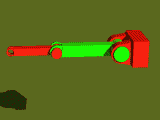
| After leaving the Properties dialog you can immediately observe a change in the drawing of the object-axes. Locked axes are set off against the unlocked axes in a grayed style instead of the usual axes colors. Pull now again at the level object "arm1". It rotates now only about the y-axis and the movement stops in the vertical position at the top and at the bottom respectively.
|
|
|
|
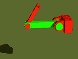
| Now let's add a little bit to the complexity of the model by adding another joint object (file "ik_2_joints.cmo").
|
|
| Select the new object "arm2" and call up again the Properties dialog. Lock again the x- and z-axis. For the DOFs we enter this time a little bit greater range of ±120°, so that the lever "arm2" can move exactly on both sides until he hits the base of the lever "arm1".
|
|
|
| Let's focus again on the difference between the two Kinematic modes. With Forward Kinematics you select an object in a hierarchy of joints. When you move your mouse in a certain direction, then the selected object tries to follow that movement by a rotation around its object-axes. All objects subordinated to this object will execute exactly the same rotation, similar to the rotation of an object group about the object-axes of a reference object.
|

|
| The idea behind Inverse Kinematics is a different one. You mark an object at the end of a chain of jointed objects as reference object, in our example "arm2". Then you select with a second mouse click, while simultaneously holding the <Ctrl>-key pressed, the top most object in the hierarchy that you want to include in the movement - here "arm1". The object-axes of all marked objects - except those which had been locked for Kinematics - are drawn. Additionally a thick line between the individual joints is drawn to emphasize the connection of all involved joints. If you give now the direction of movement with your mouse, then "arm2" tries again to follow the movement, only this time all marked joints participate in the movement. This way the two levers of our model can be stretched or bent with simple mouse movements in the respective direction.
|
|
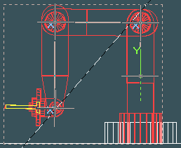
| Finally again our example from the robot tutorial (file "projects\ik\ik_robot.cmo) with all DOFs already entered. If you select the tongs object at the head of the robot and pull at it, then a movement will be calculated that involves rotations about 3 hinge joints and 1 rotational joint at the base of the robot at the same time. The pair of tongs is locked for Kinematics and therefore will not it self be rotated, but it has unlocked parent objects serving as joints and the movement is passed on to them. This is always of importance when you subordinate objects to a parent object serving as a joint, but don't want the subordinated object to be part of the chain of joints, e.g. if the added object is only an addition to the construction of the parent object.
|


